
I've been cleaning my cabinet and I've found one of my old projects. Projects without sense. Well, with a lot of sense, but without one at the same time. The idea of the project was good. It has a lot of sense to me. Assumptions... well, they were not that bad. But then, constraints have happened.
Welcome to a long story about time measurement, photography, photo cameras, how to and most of all, how not to do electronics.
2006 - that year is etched on boards. Back then I've used Chinon CM-4 or Chinon CG-5 camera. I'm pretty sure, that I had sold Zenith TTL some time earlier. The Chinons have Pentax's K bayonet, which stays with me up to now. In that time I've wanted to know everything about photography. "I want it all and I want it now". Gear included. Chinon as a brand was never really acclaimed and it was not widely recognized, especially in Poland. But their gear was very competitive.
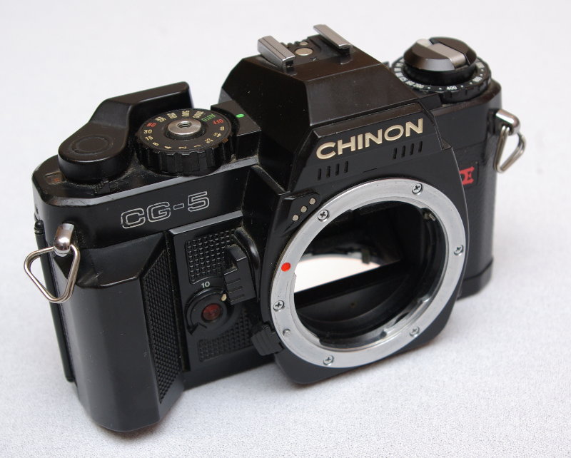
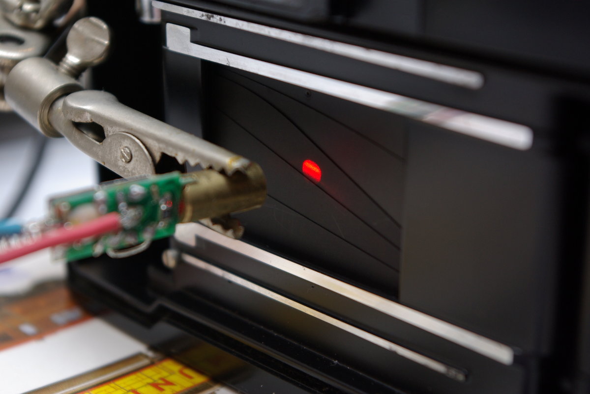
I'd say, that CG-5 was no worse than Pentax ME Super. Well, it's 2018 and I'm still using this camera and it works flawless. But then, the gear and the knowledge obsessions led me to the desire of knowing how precise the shutters actually are. I'd thought about a simple, but in my opinion ingenious, solution. Let's put a phototransistor behind the shutter and a light source in place of the lens. Shutter opens, phototransistor is floodlit, starts connecting and enters saturation, time counting starts, shutter closes, phototransistor cuts off, time counting stops. We have the result.
Something like that (with the "slight" difference that this is 2.0 laser blaster edition build for the need of this post):
Aaaand that was the point, when the inevitable happened. The theory had met practice and things started to collapse.
Everything looked good on paper. Phototransistors have on and off times very simillar, so the error from it zeroes. I took those, which worked in infrared, so daylight wouldn't be a problem. Maximum working frequency for phototransistors which I took into consideration was about 100kHz.
The cameras which I had, have the shortest time equal to one thousand of a second. Much better gear have 1/4000 or even 1/8000 sec. So I considered 1/8000 as the shortest time to measure and I rounded it to 1/10000 - which is 100 microseconds. I set a clock frequency to 100kHz - ten times faster than the shortest time to measure, equal to maximum sensor working frequency. For shutter times I was most interested with (1/1000 and slower) it was one hundred times faster. I've seen the world in bright colors. Now, I see it kind of different 😉 But still - to count 1/1000 and longer - it was enough. There was one more error to compensate - shutter curtain speed. I compensated it easily - with the assumption that front and back curtail travels with the same speed, so the error zeroes. Well, let's not dig deeper, please...

.. because then we'd know, that I was not fully aware how focal-plane shutter really works. I used to be pretty sure, that it opens (and closes) so fast, that even in the shortest times the entire frame is fully exposed. That is true for up to 1/250 in high end cameras. When the time is shorter, both curtains travels simultaneously with a gap between them. It has some side effects - objects which move fast and perpendicular to shutter motion become distorted. Simple flashes cannot work with that fast shutter times and of course the phototransistor in my device is not lit evenly. It stays saturated longer than it should.
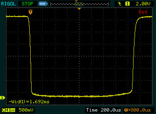
But the measurement method is not that bad. If you use point light as a light source (like laser pointer) - the results are more trustworthy (but still not good enough for the fastest times). Unfortunatelly, the idea of using laser pointer is relatively new to me... but for the sake of science (and fun) I've build a simple system with an oscilloscope as a counter. Earlier you've seen a measurement of 4 seconds exposure. Now to more interesting ones, like 1/1000:
My conclusions from the play time:
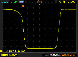
- it is much better to place the sensor in the place of a lens, and a light source behind the shutter. Just look at the oscillograms below. I don't know what makes that difference:
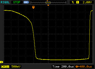
Signal slopes - detector behind the shutter Signal slopes - detector in place of the lens - the geometry is crucial - if the shutter is skewed to the light beam, we have another errors:
Shutter skewed to light beam Even slight displacement of one of the elements can result in tenths to hundreds microseconds difference.
- it is pretty good method for longer exposures. Below are 1/60 s (the only mechanical time in CG-5) and 4 seconds:
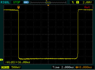
1/16 exposure 
4 seconds exposure
At last but not least - another movie, quarter of a second exposure. Pretty accurate I'd say:
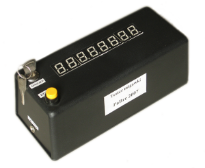
Enough about photography. Lets talk about electronics. I named my project as "The Shutter Tester". It had never been obliged to look like on the above movies. It had only have to count time (in tenths of microseconds) and display it. I've wanted automatic range switching and 4 digit display. It was supposed to be smart, simple and superfantastic. I was kind of old fashioned back then (was...) so I've planned to use 8051 microcontroller and a simple LCD display.
And that was a good idea.
But then a "digital circuitry" college project happened. So I decided to kill two birds with one stone and adapt my project to the college constraints. The nightmare had begin...
Programmable logic was forbidden, microcontrollers, microprocessors - not allowed. Everything sophisticated enough to make this project pleasurable - banned. So in the not so beginning of 21st century I could use logic gates, counters or even multiplexers! Back to 1960s'. I dropped the idea of using LCD. I used the seven segment LED displays and I have to admit - they still look gorgeous. Automatic range - no, thank you. I've had the idea how to do it, but making it physically didn't sound fabulous.
Here the math kicked in. I wanted the counter display resolution to be 10 µS. Single range. So, for one second I need six digits: 1 s = 100000 x 10 µS. I needed longer exposures, so upper limit of 99 seconds looked reasonable. That needs 7 digits. But it's odd, so let's use 8.
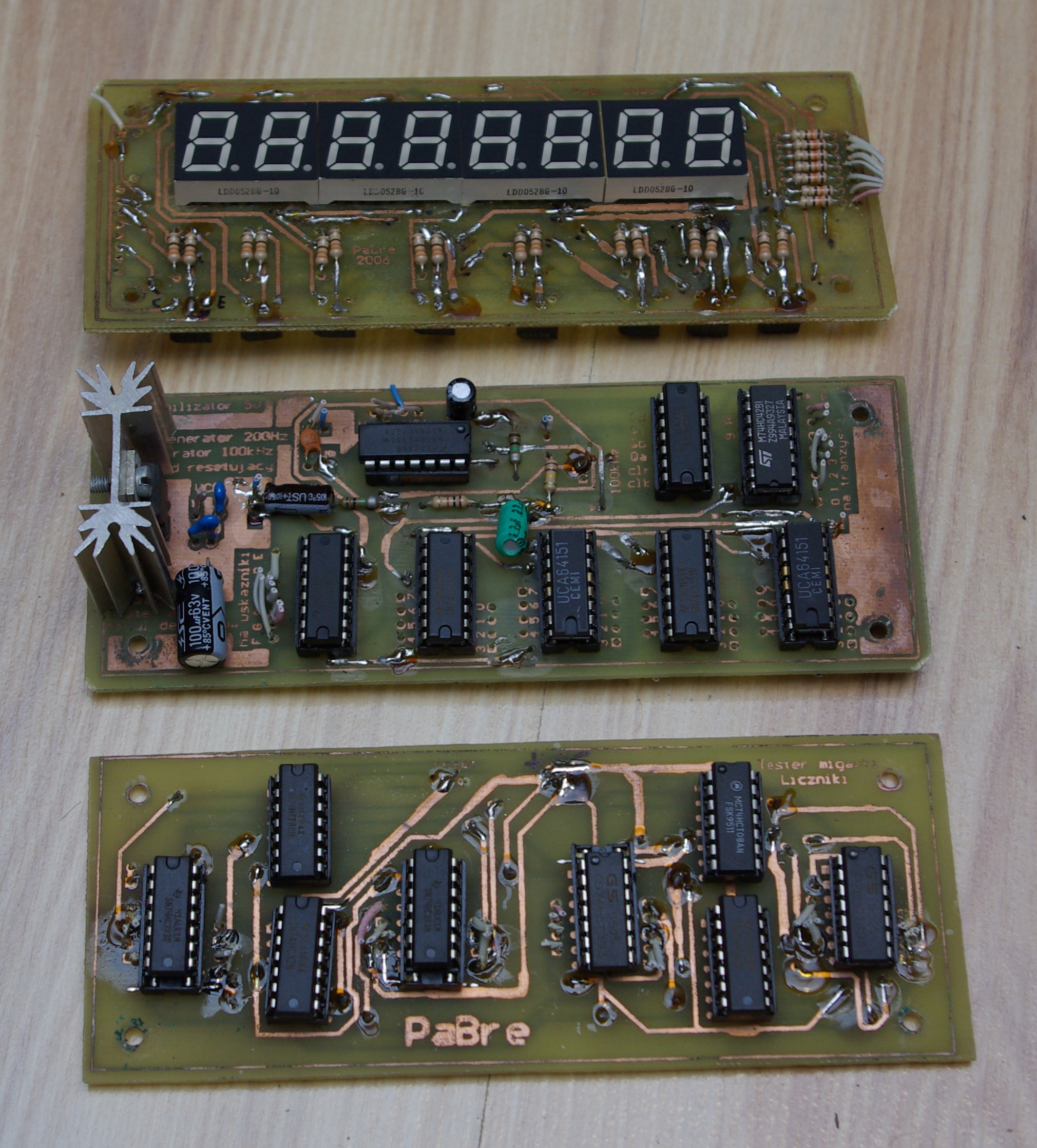
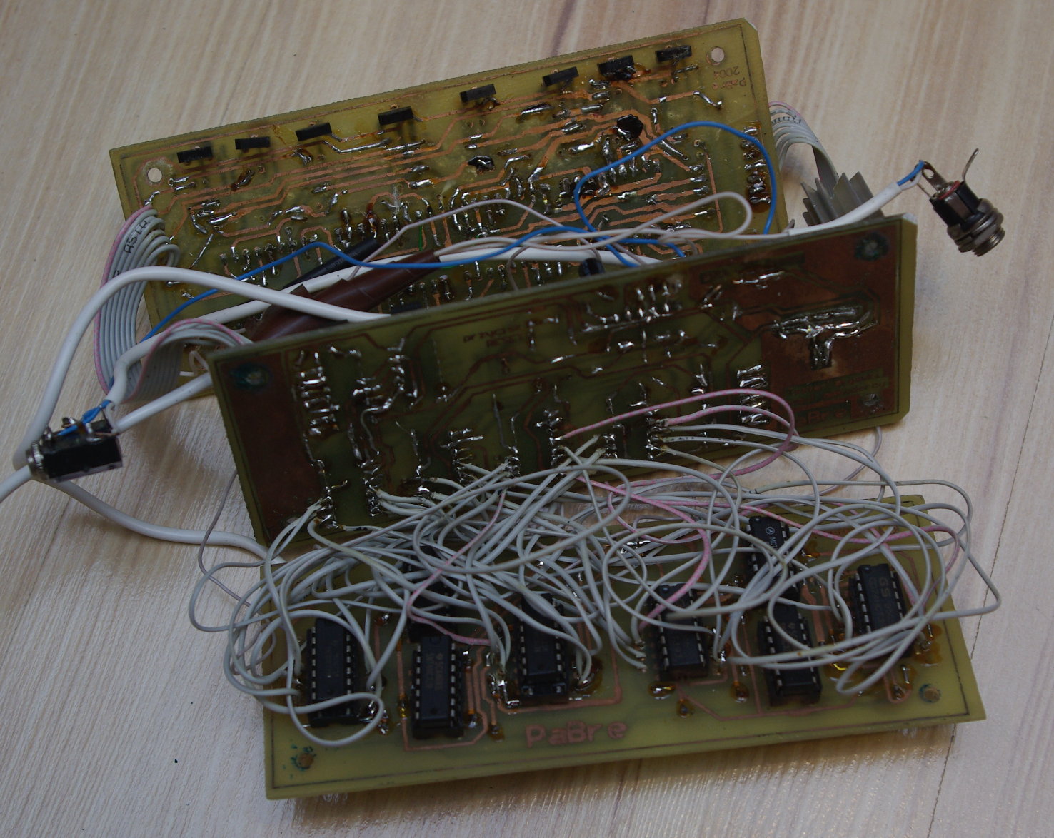
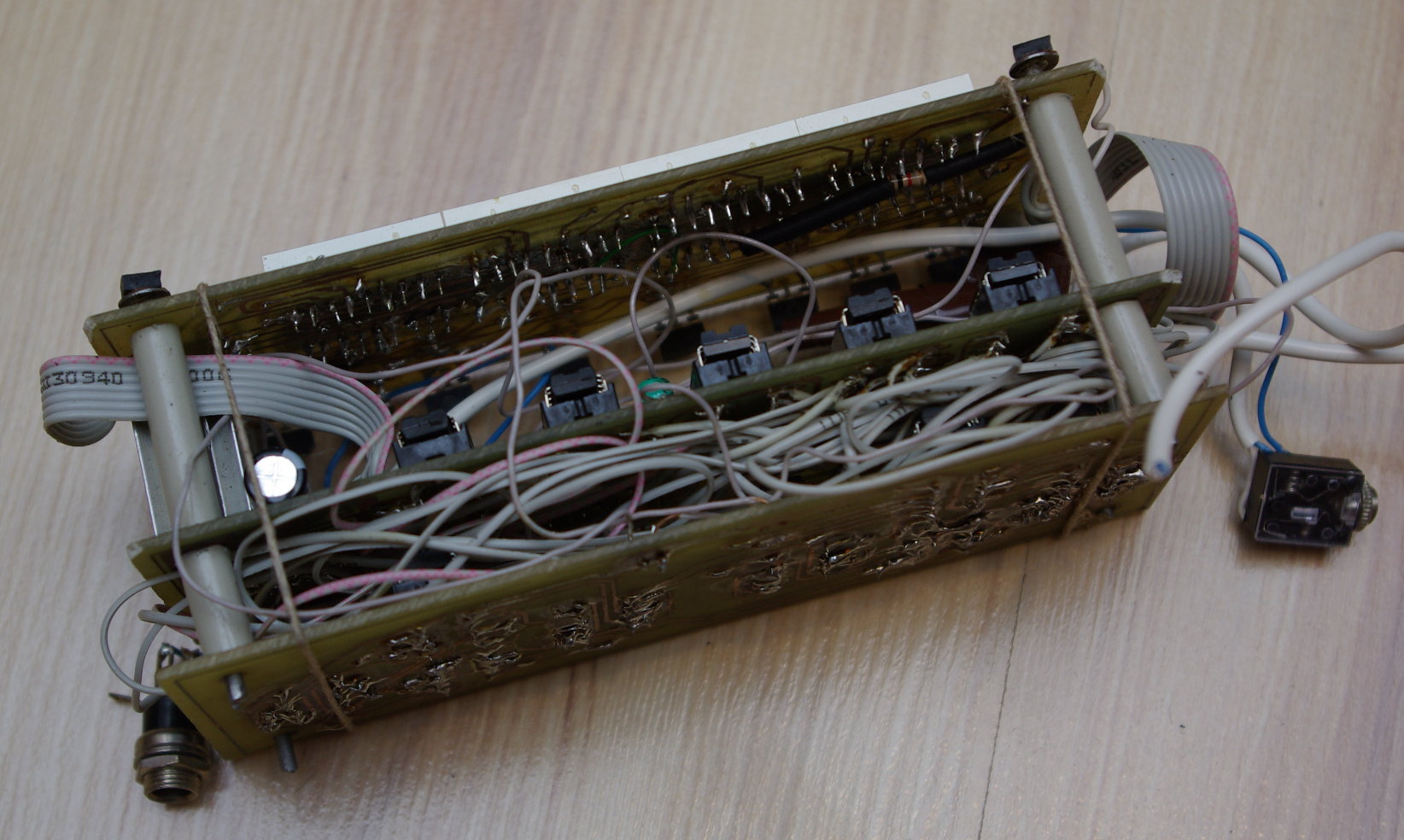
And it started multiplying... 8 digits means 8 seven segment decoders... no, too many, lets multiplex it, one multiplexer here, one there, a decoder here, maybe generator, some counters... and I finished witch 16 integrated circuits. Each of 14 to 16 leads. It hadn't look bad on the schematic. But in reality... I won't leave it to your imagination - look at the photos and cry with me.
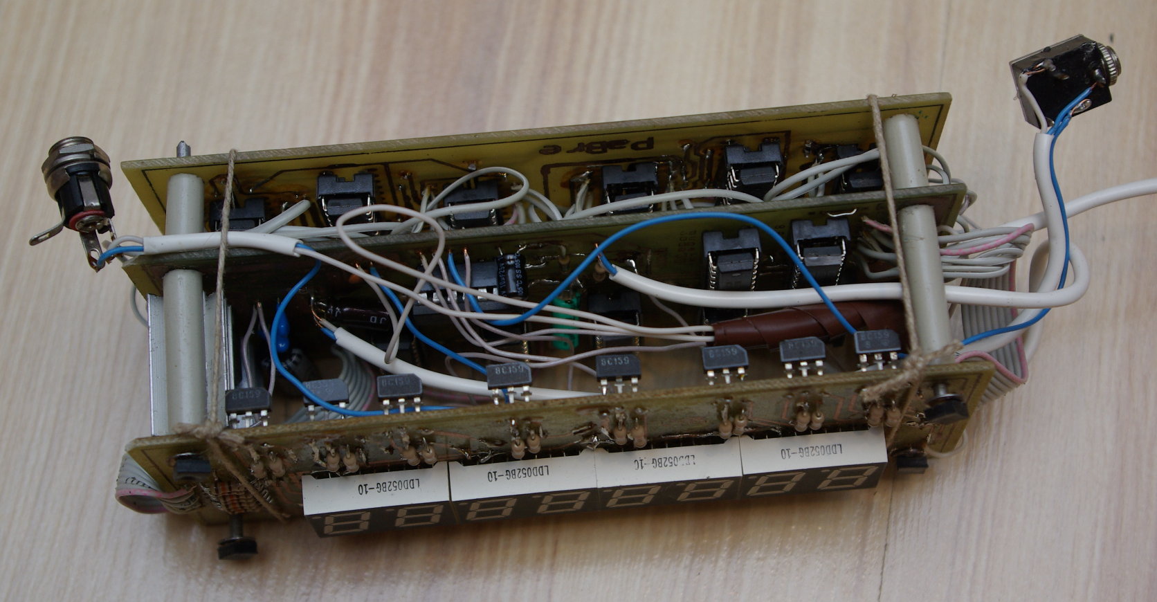
Another "bright" idea of mine: the device has to look nice. So the case would be as small as possible. Two dimensional project started evolving into 3D puzzle. Three double sided circuit boards with elements on both sides. Imagine how much "fun" I had while soldering and trying to start up that thing. I only had a multi-meter then.
The most valuable lesson from all things related to this, for me, was a little awkward. I've lost a lot, and I mean - A LOT, of time for finding and solving some weird circuit problems. Af first glance everything was working as intended, but from time to time something strange happened. Even the ICs' truth tables seemed wrong. Who was the culprit? It turned out to be the soldering paste. I used to use ICs from the epoch, as well as soldering paste. It was old, brown old. It was so old, that it had developed consciousness. Mind works on electric impulses, so was my soldering paste. It conducted electricity. A little, but enough (tenths to hundreds of kiloohms between adjacent signal paths).
After that, everything else was a piece of cake. The device was working, the project was rated positively and I've never ever returned to it.
Now, while taking the circuit apart I see how clumsy it was. It's not that I'd made mistakes. Those were mistakes to make. The problem is, that nobody really noticed and never pointed them. There was no atmega inside so it was good enough...
What hurts most:
- 7805 voltage regulator worshiping. I was used to put it everywhere. EVERYWHERE. I'd build circuits powered from DC, but I'd wanted to have my own, the best, 5V DC.
- no noise suppression, power lines drawn with fantasy, not with sense. Sixteen TTL ICs in the device, no capacitors near power pins... (probably only because many of them were HC / HCT it ever worked)
- clock source build over Schmitt trigger with RC components. In a device, which the sole purpose was counting time as precise as possible...
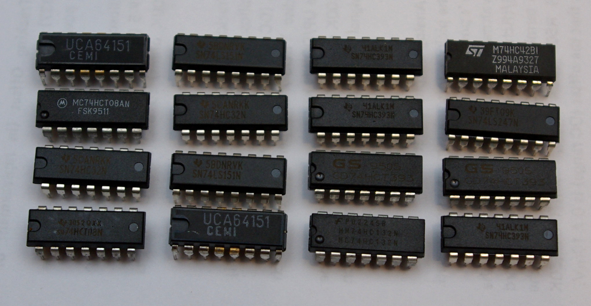
- eclectic use of IC series. I see 74 LS, HC, HCT and 64 from CEMI which are nobody knows what - S, LS, AS or even standard ?
- lost time. The design process, including simulation in Electronics Workbench (beloved version 5.12) took maybe one day. But building it and trying to run it in its physical form took forever.
But there is also a bright side:
- I gained an unique knowledge about the conductive soldering paste
- that thing REALLY WORKED!
- I have gorgeous LED displays on a board, which can be reused
- I had an excuse to play around with a laser pointer and an oscilloscope
- my Chinon camera is still in shape
- I've cleaned my locker
- I'm not into 7805 anymore (neither into LM317)